Basys 3 FPGA VGA Demonstration
Introduction
This Verilog project is meant to demonstrate the running of a VGA monitor using the Basys 3 FPGA board. Upon plugging the Basys 3 board to a capable VGA monitor, a 640 x 480 pixel display will appear with a white box in the center of the display. This box then can be moved around the monitor using 4 buttons on the Basys 3 board. These buttons represent UP, DOWN, LEFT, and RIGHT. Each button press will move the box 20 pixels on the screen.
Design
To start the design process, research on how to run the VGA display was needed. The Basys 3 board has decent documentation on how to run the display and is what was used. To run the display, two counters are needed, one for the vertical pixels (the rows) and another counter is needed for the horizontal pixels (the columns). Once the counters are running, at various subsets of the full counter, different data should be output. For this reason, what will be called the H_cnt and V_cnt are the most important part of running the VGA display.
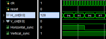
According to the Basys 3 documentation, to run at 640 x 480 px at a 60 Hz refresh rate, the H_cnt will count up to 800 (or 0-799) and the V_cnt will count up to 521 (or 0-520). Each counter will run at 25 MHz. To run the display, Each counter has four distinct sections each will its own purpose. The sections are the Sync section, Front porch, Display time, and the Back Porch. The count ranges for the horizontal are 0-95, 96-111, 112-751, and 752-799 respectively. The count ranges for the vertical are 0-1, 2-11, 12-491, and 492-520 respectively. During the sync section two synchronization signals, H and V sync will need to be HIGH and LOW during all other sections, see below. The section display time is when four bit signals for Red, Green, and Blue need to be output to write to the screen. If synchronization is kept and the display is running, these sections of each counter is where the white box will be written to the screen
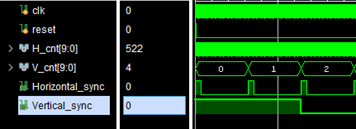
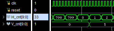
Knowing what needs to be done, the counters were the first things to be made. Each counter needs to run at 25 MHz so a clock divider was needed. The Basys 3 board has a 100 MHz crystal oscillator clock and that is what will be used. A simple clock divider was made to divide the frequency by four and will serve as our 25 MHz clock. For each the H and V_cnt a 10 bit register was used to count from 0-799 and 0-520 respectively. The horizontal count updates every clock period, but the vertical only counts up after each horizontal row is complete. For this reason, every completion of 0-799 for the horizontal count, an output V_increment signal goes HIGH to signal to V_cnt to count up one, see below. For good synchronization with each other and the system as a whole, there is also a reset input that will set each counter to 0
The next module of the design will move around the box that will be created. To do this, a set of bounds will be used to serve as where to write the box. These bounds are H_lower, H_upper, V_lower, and V_upper. For example, if H_lower = 0, H_upper = 50, V_lower = 0, and V_upper = 50, a 50px by 50px box in the upper left corner of the screen could be made. To move the box around these bounds shift according to the input, UP, DOWN etc. For example, if an UP signal is received the vertical bounds need to shift down 20 px. This same logic is used for DOWN, LEFT, and RIGHT and will move our box around the screen based on these inputs. To start in the middle of the screen, a reset signal is used to reset the bound to put the box in the middle of the screen.
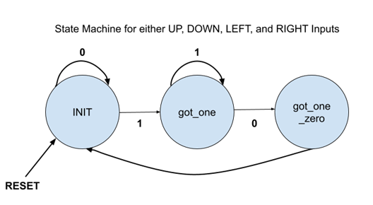
Because the Basys 3 board uses physical buttons, accounting for button debounce is necessary. To do so, a 10 Hz clock module will run a 0-1-0 state machine to signify a button press, see below. This state machine will serve as our movement signals in the movement module. Running the state machine at 10 Hz will filter out any unwanted button bouncing. The side effect of running the clock so slow is that the button will need to be help for >100 ms. It is assumed that the user will press the button for at least that long.
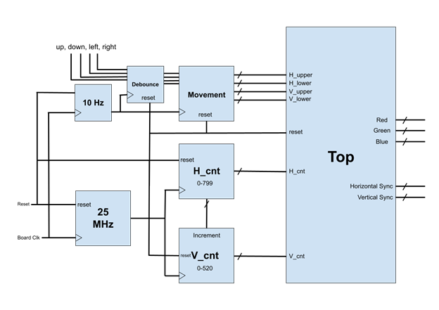
With the counter and movement taken care of, all that is left to establish is the top module. In the top module a grouping of ternary statements is used to setup the horizontal and vertical sync as well as the RGB output. If the positioning of the counters is in the range of the square’s bounds, the RGB output is set to white otherwise the output is 0 (black). See below for a complete block diagram of the design.
Results
The design was then tested with a testbench making sure the timing and RGB outputs were correct. After everything was checked, the code was synthesized and put onto the Basys 3 board. The user was now able to see the white box and move it around using the appropriate buttons. The project uses 0.61% (126) of the boards LUTs and 0.28% (116) of the Slice Registers with a maximum clock frequency of 100 MHz.
Overall the project moved fairly smoothly but was not free of hiccups. The setup of the design worked well and if properly implemented, works. If I were to do the project again, I would setup more test scenarios in between steps of the design process. Isolating problems in this way would help speed up development and lessen frustration in debugging. In addition, I would also comment my code along the way rather than at the end. Coming back to your own code and not knowing what it does is not ideal. To improve the design I would clean up the code a little by reordering my modules to make more sense. I would also add more features to the design like color changes or some other functionality. Something like an image reader, instead of the square, would bring a dynamic element to the design.