Customizeable RTC using Large 7-segment Displays
Introduction
The classic 7-segment display is relatively small at only about 0.5” x 0.5”, but it has a relatively simple construction. Put 7 LEDs in the right place and you can make your very own 7-segment displays. This is intriguing, how big could you go? In this project, that question is answered. Although these 7-segment displays could be used for a variety of different tasks, the use case in this project is to display the time using a RTC (Real Time Clock). The segments themselves are fully modular so repurposing them is trivial.
7-Segment Design
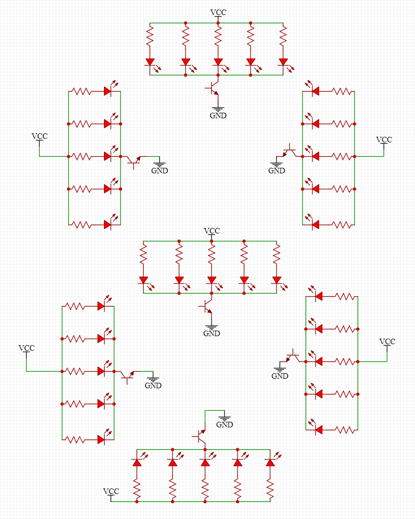
The classic 7-segment display has seven different discrete LEDs each individually controllable. The goal is to simulate this effect, just larger. To do this, instead of a single discrete LED 5 for each segment will be used. To control all the LEDs in tandem, a simple NPN BJT will be used for each segment. To drive the LEDs it might be tempting to use a single small resistor for each segment, but this will result in current imbalances that will make the LEDs have different brightnesses, this is not ideal. Due to this limitation each LED will have its own current limiting resistor.
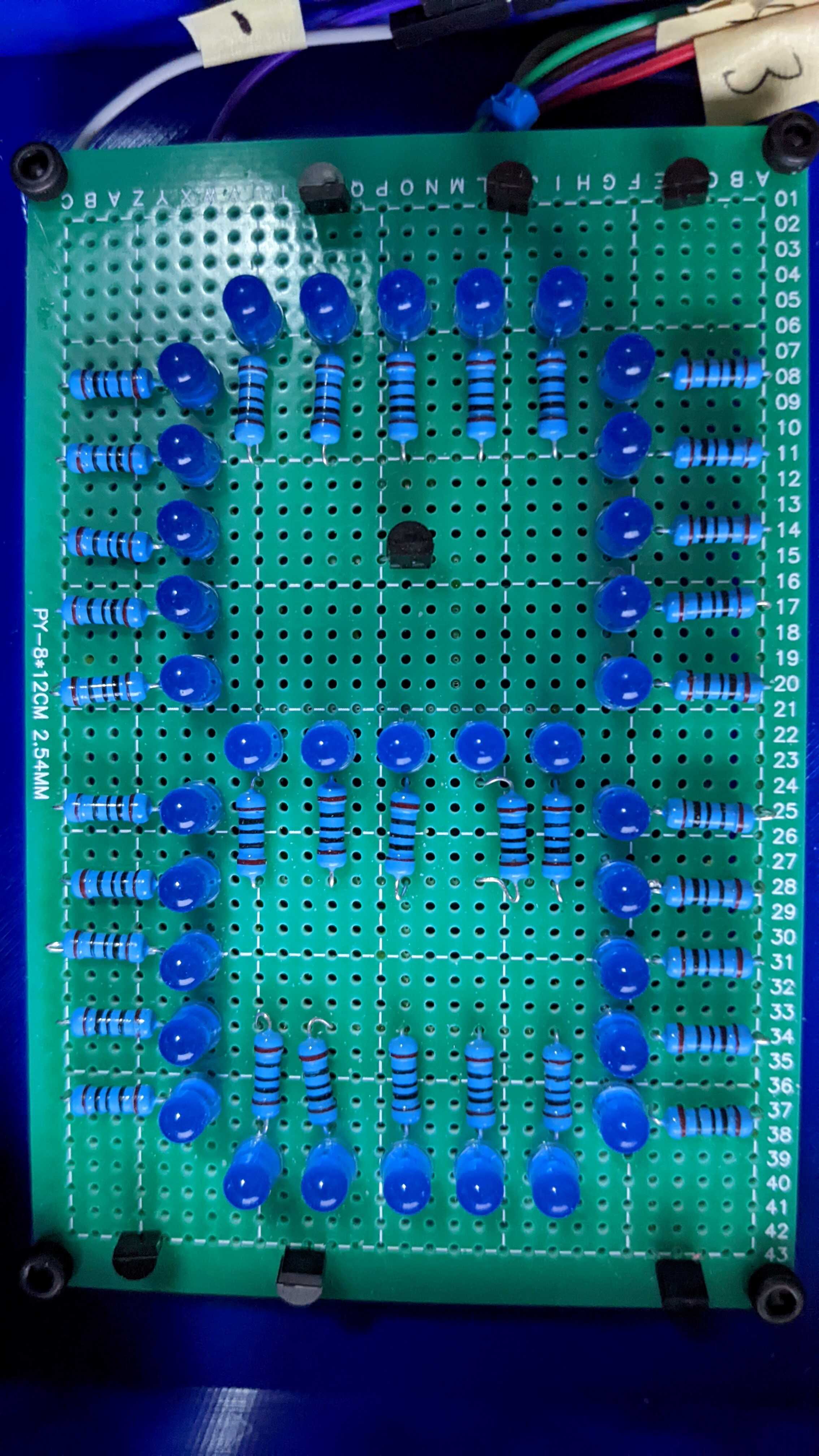
The schematic and implementation for each 7-segment can be seen below:
7-Segment Clock Design
To demonstrate using the large 7-segment displays a programmable clock will be made. This clock will have a RTC to keep accurate track of the time and a Raspberry Pi Pico to drive everything. Specifically the use of some 74HC595N shift registers will be used to limit the amount of GPIO ports needed to drive the 7-segment displays. To add more features to the clock, there will also be a dimming potentiometer that will modulate the output to dim or brighten the lights. Along with the 7-segment displays, the control board will also have a LED matrix to represent a colon to indicate the separation between hours and minutes. The final control schematic is as follows:
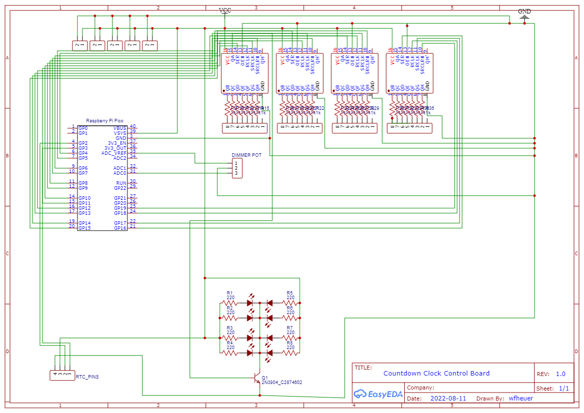
Due to the amount of LEDs in this design (148 total) a normal USB power supply will not suffice. At full brightness the max current draw is going to be ~2.5A. To supply the power a 5V 5A power supply will be used.
Fabrication
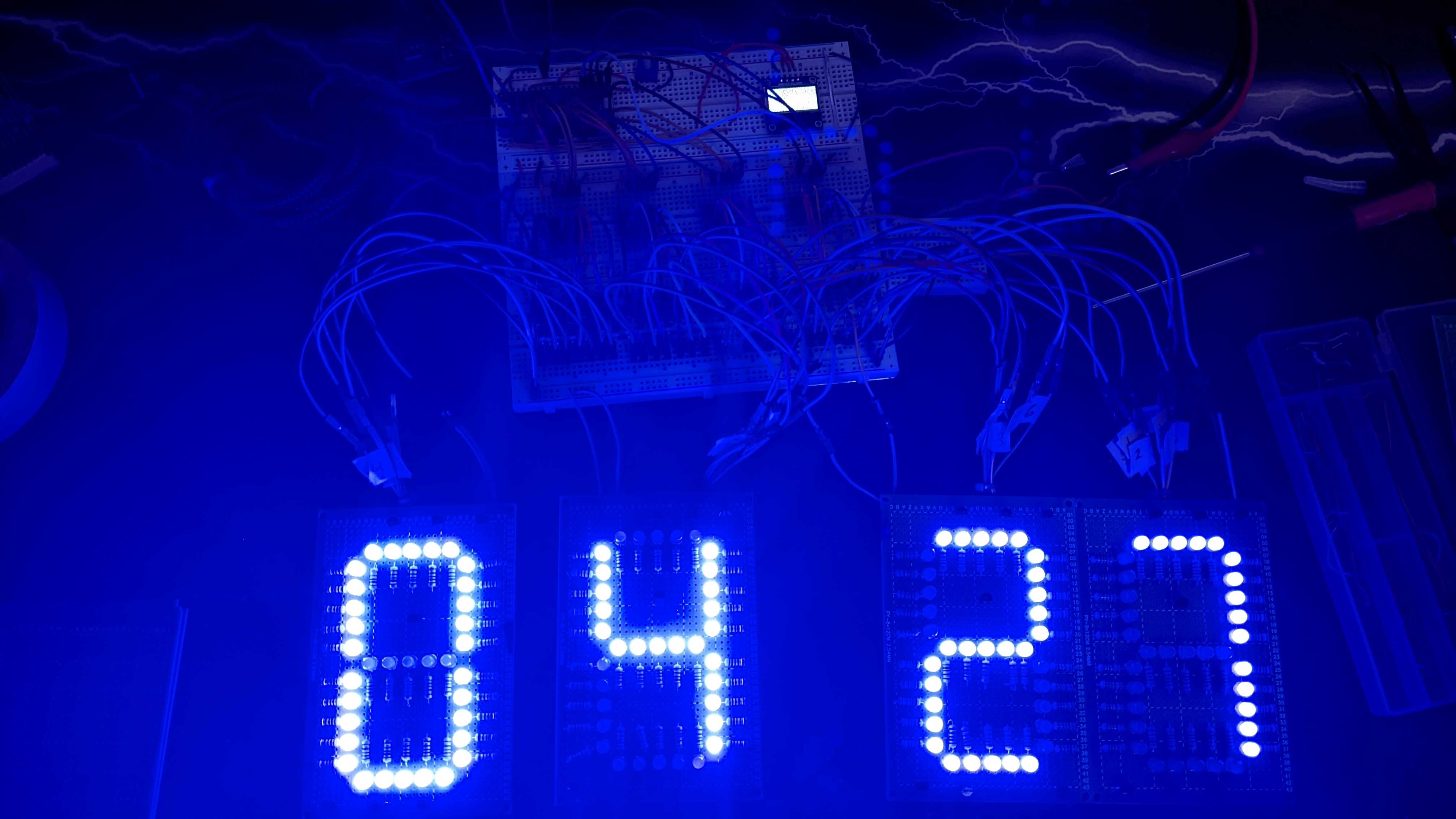
Before the design is moved further the software needs to be written and the design needs to be validated. With the help of the Raspberry Pi Pico SDK the software was quite simple. Once the software was written it was time to test. Here is the result after laying the design out on a breadboard:
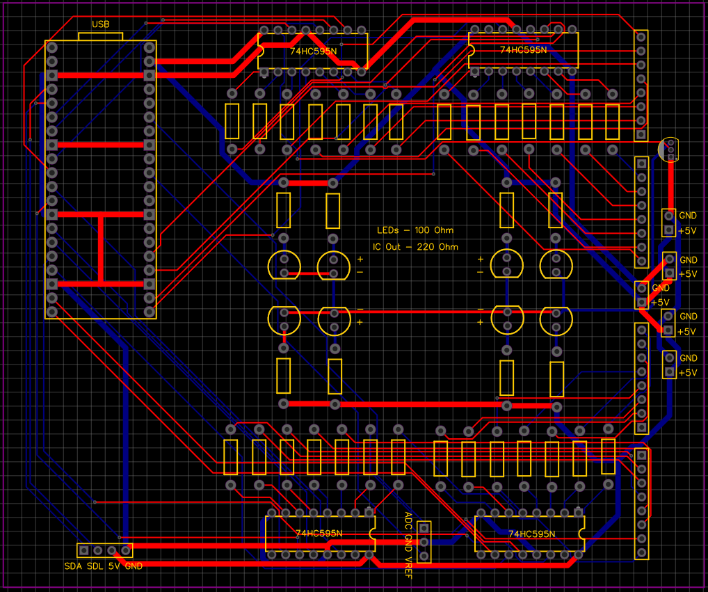
Due to the complexity of the control board, it is best to create a PCB. Here is the layout:
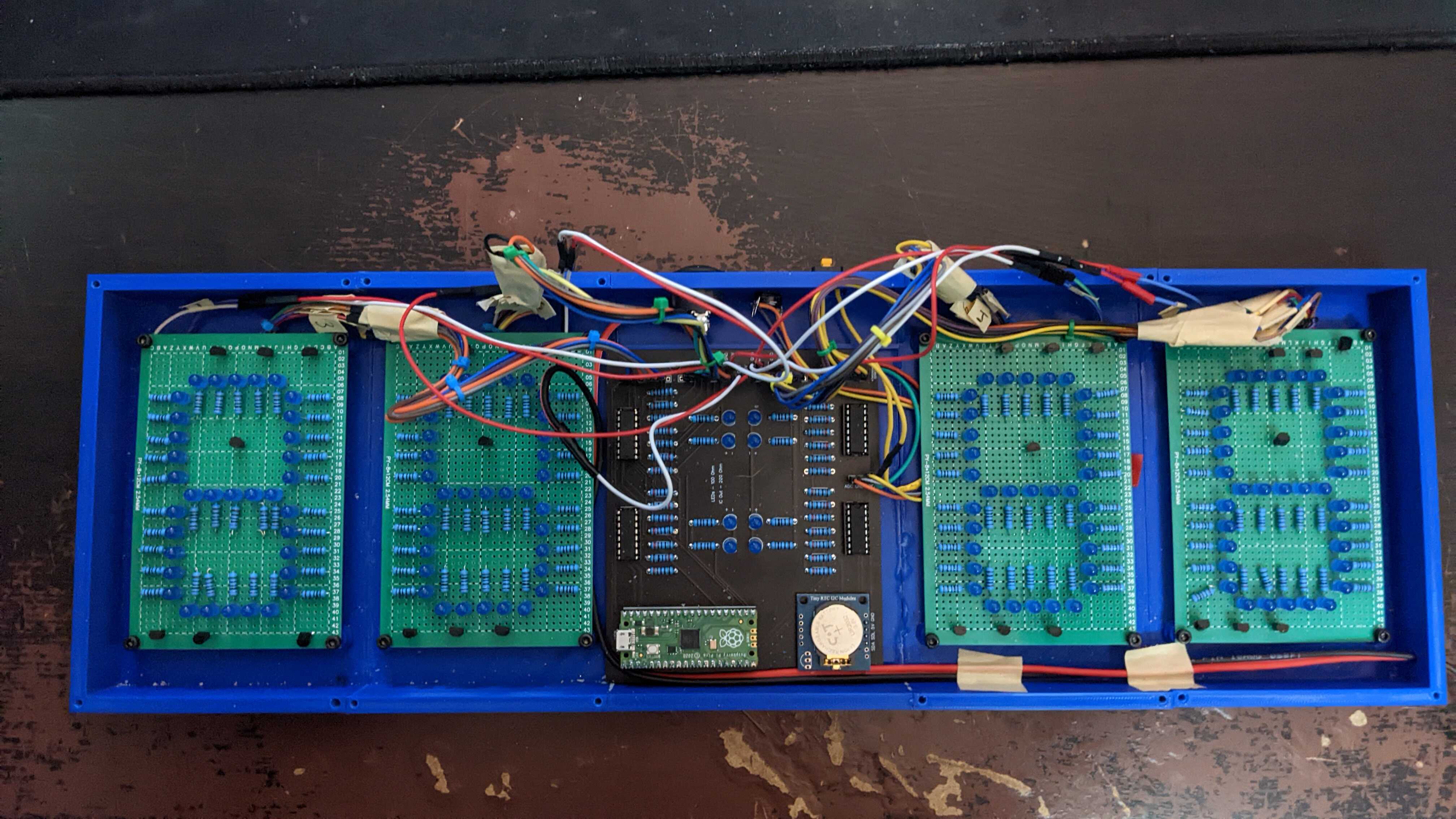
Once the PCB is received, it is time to start making the final version. To house both the 7-segments and the control board, a rectangular prism will be constructed that will have a row of 7SEG - 7SEG - Control Board - 7SEG - 7SEG to give the time. Additionally, a power switch is added. After many hours of 3D printing the housing the housing looks like:
Conclusion
Due to time constraints the final design has not been completed, but the clock is fully functional. The wires will be shortened and the top will be added, at that point the design will be fully complete.