LED Cube
Introduction
This project is one of a few LED based novelty display objects that I have created. The final project is a fully self contained, battery powered, cube of RGB LED panels. All of the LEDs are individually addressable and can be controlled via a web interface.
Design
There are three major components of the LED cube, a universal LED panel, the LED driver board, and a 3D printed support strucutre to hold the cube together. For each cube there are six seperate panels and only one controller.
Panels
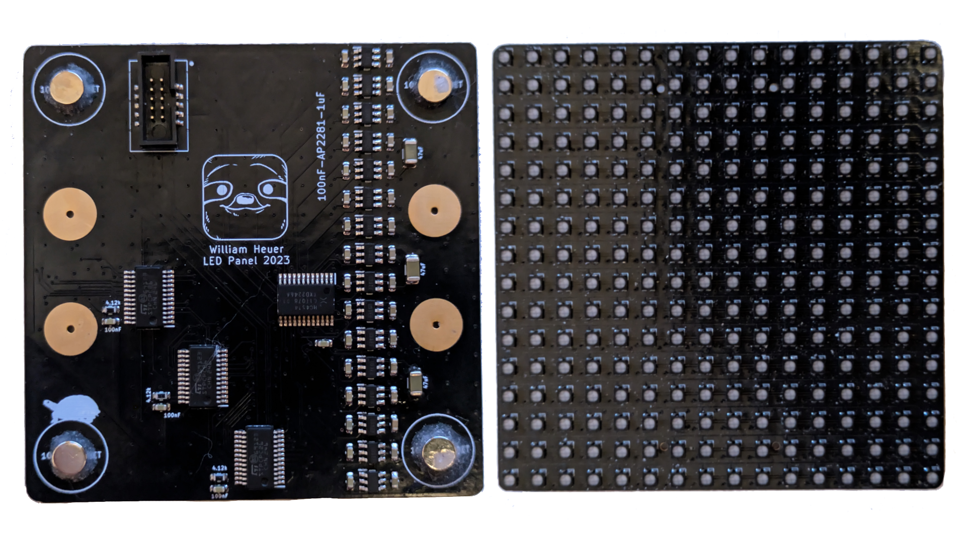
Each panel of the LED cube contains a 16x16 common cathode RGB LED array totaling 256 RGB LEDs per panel and 1536 total RGB LEDs for the whole cube. To drive the LEDs each panel contains three constant current 16-channel LED drivers that are row multiplexed using 16 high side load switches which are selected by a 16 bit multiplexer. This configuration allows us to use traditional scanning techniques where we only drive one row of LEDs at a time fast enough to trick the human eye into seeing a solid picture. The nature of driving the LEDs this way also means that the average current consumption for each panel is only the sum of 16 RGB LEDs, not 256.
Controller
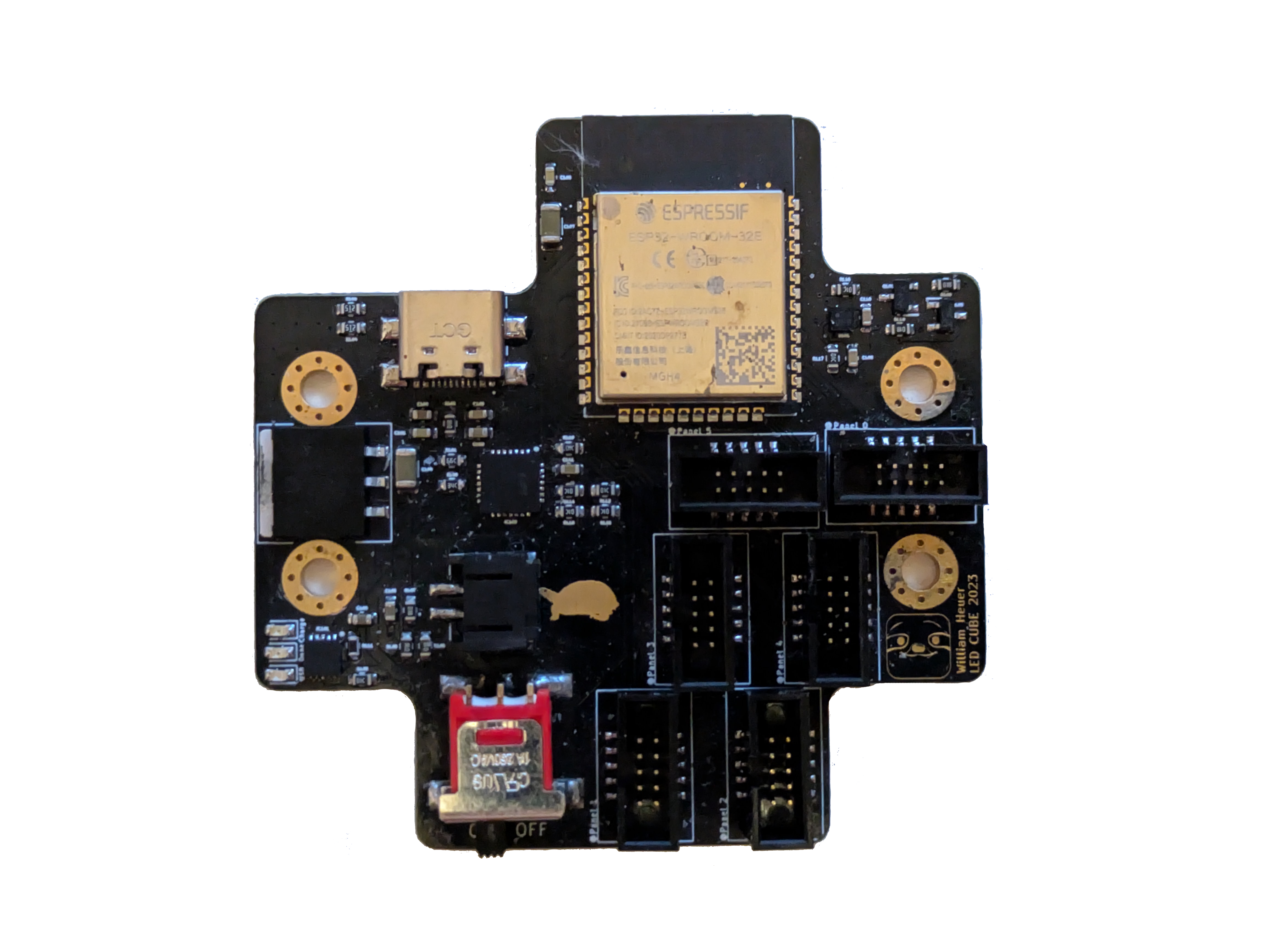
The controller consists of the required hardware to drive and power the LED panels. This includes an ESP32, battery, battery charging circuit, USB communication, six dedicated panel headers, and a beefy linear regulator.
A 3-axis accelerometer was also added to the controller board for LED effect development but at this time has not been utilized in any meaningful way.
The controller's main task is to continously provide the scanning and data signal to each LED panel. To do this, the ESP32 provides a dedicated serial data stream for each panels LED drivers and a shared set of signals for the row multiplexer.
Mechanical Design
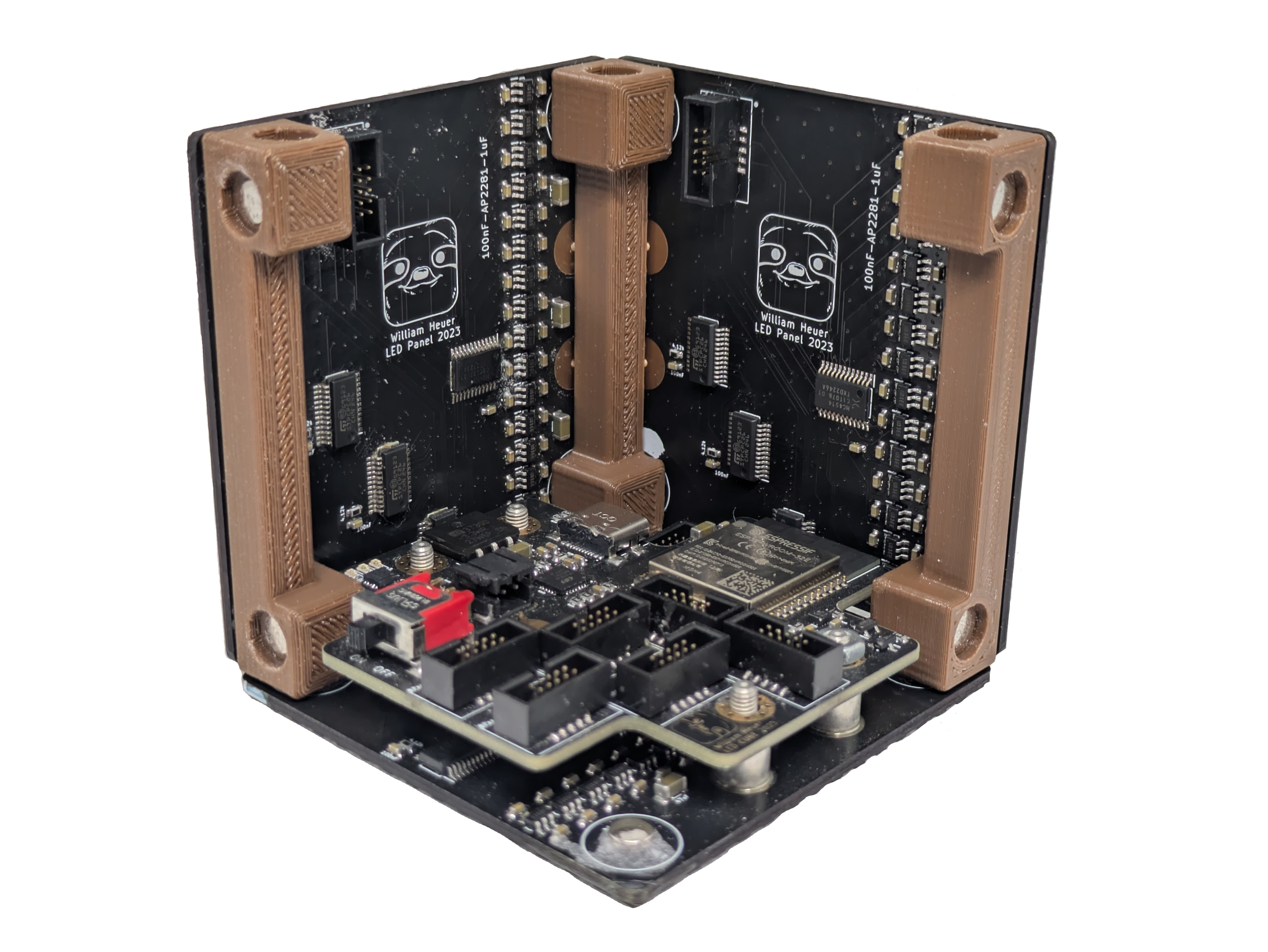
To make the cube out of the panels and controller, four 3D printed columns were used. These columns are fitted with small neodymium magnets that mate with identical magnets glued to the panel PCBs. Additioanlly, to attach the controller PCB, solderable standoffs were added that allow for the controller to be directly mounted to one of the outside panels.
Firmware
As noted before, the main goal of the controller's ESP32 is to properly send data and control signals to the LED panels according to the current LED effect. Additionally, the firmware implements proper battery monitoring and charging control. To connect to the outside world, the firmware also configures and hosts a simple web interface on a nearby local network. For ease of setup, the firmware provides a WiFi manager to bootstrap any network connection as well as an mDNS service to have a name based connection rather than having to obtain an IP address.