Fully Automated Lock Box
Executive Summary
The goal was to design and build an automated, secure, storage system for a phone or similarly sized object. The system would automatically open and close selected drawers and allow the user to set a passcode to open the drawer later. The design explained below meets this goal and all customer requirements.
Requirements
- 1. Operate using an ARM Cortex M4 processor
- 2. Operate drawers autonomously
- 3. Be powered from a battery lasting a minimum of 2 hours standby time
- 4. Have a power switch
- 5. Have a master password for both drawers
- 6. Have an LCD screen and keypad for drawer and password selections
- 7. Gather and display temperature data inside the storage system using a temperature sensor and the LCD
- 8. Not take more than one minute to open or close the drawer
- 9. Fit phones up to 7 inches long and 4 inches wide
- 10. Secure drawers when drawer is in locked state
- 11. Keep locked drawers locked when powered off
- 12. Have external lights for when dark
- 13. Have drawer indicator lights for whether the drawer is occupied
- 14. Appear off until user approaches
Design Overview and Analysis
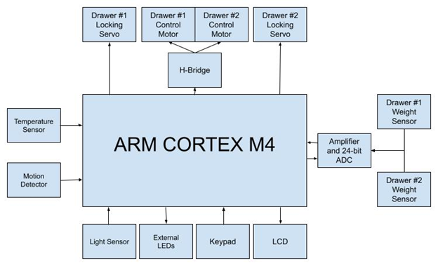
This design is best explained through an example of use. First, a user walks up to the system. A motion sensor recognizes this and initializes the components previously turned off to save power. The user chooses a drawer using the keypad as explained by the LCD. Assuming it is empty, the drawer is then opened using a rack and pinion gear system driven by a DC motor. After the user places a device in the drawer, the device’s presence is recognized by the load cell in the drawer and the user is asked to enter a passcode which will later unlock the drawer. Once the passcode is entered, the drawer closes, locks using a servo motor, displays the temperature detected by the temperature sensor inside the system and returns to the “Select drawer” screen. If the user chooses a locked drawer, they are asked to enter the passcode associated with that drawer before it will unlock and open. The system waits for the device in the drawer to be removed, indicated by the load cells, and automatically closes the drawer. Again, the temperature is displayed, and the system returns to the “Select drawer” screen. When the user is done, they walk away, and with no motion detected, the system enters a sleep mode which disables everything except the motion sensor and STM microcontroller board. A photoresistor detects ambient light and turns on white LEDs if low levels of light are detected. Red and green indicator LEDs tell the user whether a drawer is occupied or vacant at a glance. The system takes two power sources: a 9V battery converted to 5V with a linear voltage regulator, and 4 AA batteries to create a 6V source for the DC motors. A power switch and external reset button are also included. The drawers, DC and servo motor mounts, keypad mount, and rack and pinion gear system were all 3D printed for higher accuracy. For speed and cost, the remainder of the enclosure was built out of ½” Baltic birch plywood.
System Block Diagram
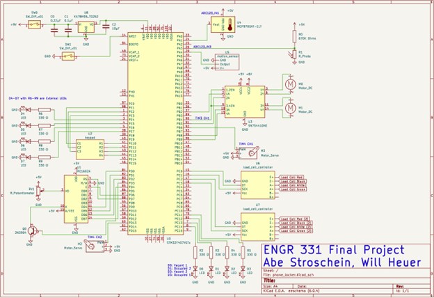
System Schematic
Design Validation
To prove the design works as intended, each step in the user interaction process was checked for a few scenarios. The main two possibilities are the user interacting with the first drawer versus the second drawer. From there, the possibilities branch into opening the drawer to place a device inside or unlocking a drawer with a device already inside. Thus, for each drawer, the system was power cycled, the drawer was chosen using the keypad and a phone was placed inside with a simple passcode. Throughout this process, the drawer opened by the system displayed on the LCD needed to match the one entered, and the drawer needed to detect the phone’s presence and close the drawer entirely, locking with the servo motor and changing the vacant/occupied red and green indicator LEDs. The LCD and indicator LEDs were checked visually, and the drawer closure was checked by whether the servo motor fit into the locking slot in the back of the drawer. If the servo did not fit, then the drawer did not fully return. To check this, the top of the drawer was removed to reveal the servo and locking slot until final testing, in which the drawer could be seen flush with the rest of the enclosure, and the servo could be heard turning within the enclosure. After that, the temperature displayed on the LCD by the system was checked to ensure that it fell within a reasonable room temperature range of 70-80 degrees Fahrenheit. This concluded the test for the first possibility of user interaction: placing a device in the system. The most common problem in this test was the load cell not detecting the device’s presence. The load cell’s thin wires disconnected easily, and trial and error revealed the external ADC performed better for use in the system when powered by Vdd instead of 5V. These were solved with extra electrical tape around the load cell’s soldered connections and switching the external ADC to run off the STM board’s Vdd pin. A recurring and unsolved issue discovered with this test is that when the system is powered on, both by a 9V battery and USB connection to a laptop, the top drawer opens without command and before setup. Because it happens before setup, this issue has been attributed to the H-bridge.
After that test, a phone was already inside and the second test, retrieving a device, could begin. Once again, the correct drawer needed to open and be indicated on the LCD and the indicator LEDs, and the load cell needed to detect when the device was removed from the drawer, after which the drawer would close, and the temperature would again be displayed. After solving the issues in the first round of tests, the main issue revealed by these tests was that the servo motor needed more time to unlock before opening the drawer, and the user needed a delay after the load cell detected the device had been lifted to remove it from the drawer. To ensure customer requirement 11, “keep locked drawers locked when powered off,” the system was tested by placing a phone inside as with the first round of tests, and power cycling the system before going through the second round of tests to remove the phone. These tests revealed that the load cells needed to be checked on startup to determine whether a phone was inside as the variables indicating whether a drawer was vacant or occupied were reset after a power cycle. After fixing this, the drawers’ occupancies were indicated correctly on the LCD and LEDs, and the phones stored inside could be retrieved using the master passcode hardcoded into the system’s software. The master passcode must be used because, like the drawer occupancy variables, the drawer passcode variables containing the passcode users set when placing a device in the system are reset after a power cycle. This was expected, however, and still fulfilled the requirement that locked drawers remain locked after a power cycle.
The remaining tests existed outside of the regular loop of user interaction, so placing and retrieving a phone within the system was unnecessary. First is the motion sensor and idle or sleep mode the system enters after a set amount of time without user interaction. This was often tested at the end of the first two rounds of tests when user interaction had been confirmed. To ensure the system entered sleep mode, the motion sensor was blocked or left undisturbed for 1-2 minutes while waiting for sleep mode to be indicated by the LCD backlight turning off. At that point, the indicator LEDs, which remain on in sleep mode to tell potential users whether there is a vacant drawer for their device, were checked to ensure they matched the current occupancy of the drawers. Then, to ensure the system came out of sleep mode, testers walked in front of the motion sensor or waved a hand in front to simulate a user walking up to the system. At that point, the LCD needed to turn on with the initial user interaction message asking which drawer to interact with, and the indicator LEDs needed to stay on. Near the end of assembly, this test revealed that the power and ground pins of the motion sensor had been connected in reverse, and the transistor controlling the LCD backlight had been connected incorrectly as well.
As the tests progress in level of importance to system use, the final test is the night lights, controlled by surrounding light levels measured by ADC conversion of a photoresistor’s voltage in a simple voltage divider circuit. The only added functionality of this test was turning on the 4 white LEDs on the front of the box, which indicated that one connection on one of these LEDs was quite loose. This was fixed with more electrical tape. However, to ensure activating the LEDs did not affect other system functionality, all above tests were run both in light surroundings and dark to test with the LEDs on and off. Comparing system functionality of these tests revealed no issues, but because it was the last test, it was noted that the LCD had become very dim despite the power source and potentiometer controlling the backlight had not been changed. After replacing the 9V battery powering the system, the dim LCD became bright again and the issue was attributed to a drained battery. Noting and solving the issue also indicated that customer requirement number 3, “the system must be powered from a battery lasting a minimum of 2 hours standby time,” had also been met, as testing lasted well over 2 hours and user interaction mode requires more power than standby, or sleep mode.
An unplanned test immediately before demonstrating the system came from fellow students’ interest in and use of the system. Thankfully, those students’ usage revealed DC motor for drawer 1 and the top left white LED for dark surroundings had both disconnected. Once again, wrapping the connections in more electrical tape solved the problems, neither of which returned during the demonstration minutes later.
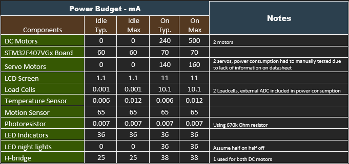
Power Budget
Raw Power Budget
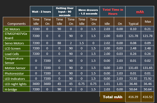
Power Budget Based on Projected Usage
Power Budget Analysis
Power Budget Analysis
The power budget shows the system requiring a maximum of 416.52mAh for a complete user interaction cycle. Assuming a 9V battery has a capacity of 500mAh, the system will last 500/416.52=1.2004 user interaction cycles assuming a 2 hour standby time. The systems efficiency could be increased most easily by using more efficient LEDs, and possibly turning off power to the H-bridge when idle using transistors.
Conclusion
The lessons learned from designing, building, testing, and presenting this project come from a mix of what worked and what could have been improved. One thing that worked well was using female header pins soldered to the perf board to connect the STM board temporarily. This made soldering directly to the STM board or using jumper wires on the STM board unnecessary. On the other hand, several of the connections soldered to the perf board were longer than necessary and made loose connections to components or other wires. A better solution would have been to group components and their wires into a series of jumper wires soldered to the component with pins that could plug into more female header pins soldered to the perf board. Better yet, having a custom printed circuit board to solder female header pins to would clean up the wiring even further. Part of the reason a PCB was not an option in this design was the time constraint. By the time the design was confirmed to work, and assembly of the final version was ready to commence, ordering a PCB would have surpassed the deadline for the project. Another good decision was using a mix of materials. 3D printed parts for the drawers and locking mechanism allowed for accuracy and replicable pieces that fit together perfectly. Using wood allowed for easy modifications and faster build time. An attaching panel was 3D printed for the keypad to secure it to the wood, which worked well, and a similar idea could have been used to secure the motion sensor and reset button better than tape. On the software side, two major ideas from the start proved quite useful. First, using git for version control allowed the design to progress in stages and roll back to the most recent working version when all else failed, which was necessary once. Second, splitting the code into separate C files and matching header files for each peripheral was useful for maintaining the code and integrating the pieces together in the main user interaction loop. Sacrificing succinctness for self-explanatory variable and function names proved a useful decision as well, making integration of all peripherals and debugging move quickly. During assembly, the schematic listing all pin connections was helpful, but it was quickly made clear that the accuracy and completeness of the schematic were vital to it being useful. As things like the power switch and voltage regulator, reset button, and LCD backlight transistor were added to the design, the schematic fell out of date in favor of testing and confirming these new pieces of the design more quickly, which caused some confusion during final assembly. The most general lesson taken from this project is that early efforts are built on in the later stages of the project. Things like having a schematic, quickly creating drawer prototypes, and ordering components early on made later stages like assembly, proving the mechanical concept of the drawer would work, and figuring out component connections much easier later.