Security System State Machine
Introduction
This comprehensive security system ensures that no one will be able to come near the treasure without alerting security. The system is split into three rings, the F ring, C ring, and the S ring. These rings have seven, six, and two sensors, respectively. The F ring is the outermost ring and has the most sensors to accommodate and will represent a first layer breach. The inner ring, C, has six sensors to alert of a center layer breach. Finally, the innermost ring, S, will indicate a full security breach of the treasure room.
Sensor Design
The security system itself will operate through the input of fifteen sensors and display the relevant output on a seven-segment digital display. If there are no security threats, the display will be entirely off. If there is a breach in the F ring, a F will appear. The same display will indicate a breach in the C or S ring with an according C or S. The system will always show the highest threat level and will not revert to any lower threat level. For example, if a C intrusion is detected, a F signal will not display even if there is a security breach in the F ring. When the threat is neutralized, there is a reset button that will reset the breach status.
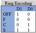
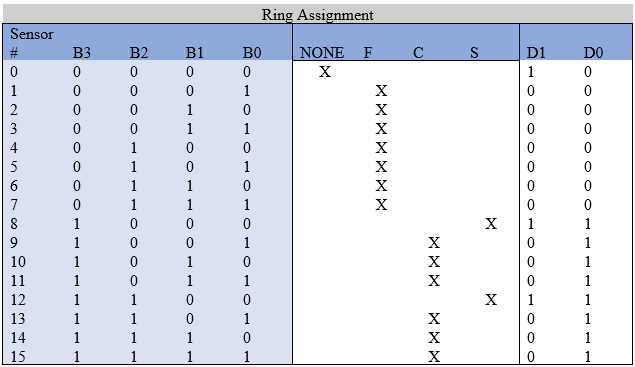
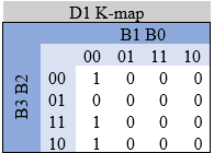
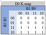
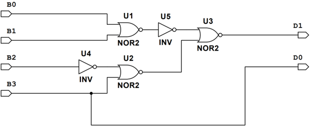
To represent the different ring layers we used two bits, D1 and D0. The encoding is shown in the tables below. Strategically placing the sensors ensures that the resulting input logic will be as simplified as possible. The final sensor placement involved simplifying D0 as much as possible. To simplify D0, F (00) and OFF (10) were used to make every D0 between the binary signals 0-7 a 0 and 8-15 a 1. This placement simplifies D0 to be merely the MSB, or B3, see below. Once D0 was simplified, the remaining C and S sensors were placed to ensure that the D1’s 1’s would be as close to each other as possible in the resulting K-MAP, see below. This ensured that the resulting logic was as simplified as possible resulting in D1 = ~B1 ~B0[ B3 + ~B2 ]. The overall placement is shown below.
Once the combinational logic equations are defined, the resulting circuit needed to be simplified to minimize the number of IC’s and the number of overall gates used. D0 is inherently simplified as B3, using no gates. D1 then was simplified by converting the AND gates to NOR gates and bubble pushing. Swapping to all NOR and NOT gates ensures that the number of individual IC’s is kept down. The result was D0 using zero gates and D1 using 3 2-input NOR gates and 2 NOT gates, below. This will cost $4.60 on its own.
Threat Level Memory Design
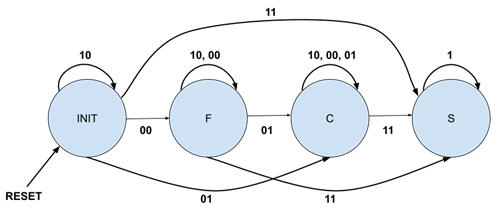
To show the highest recorded threat level, a state machine is required. The table below shows the state diagram for the machine. As shown, the binary notation of D1, D0 notating the current triggered threat level is the input between states. Using the given ring encoding, whenever a higher threat level is triggered, the next state is that higher threat level. However, upon a lower or same level threat being triggered, the next state is the same as the current state, so the machine “remembers” the highest threat level.
The state table was then derived from the state diagram below. The first state table is shown with the next state flip-flop output values S1n and S0n. This version of the table is shown below aswell. The final version of the table replaces these output values with the required input J and K values. The final version of the state table is also provided below.
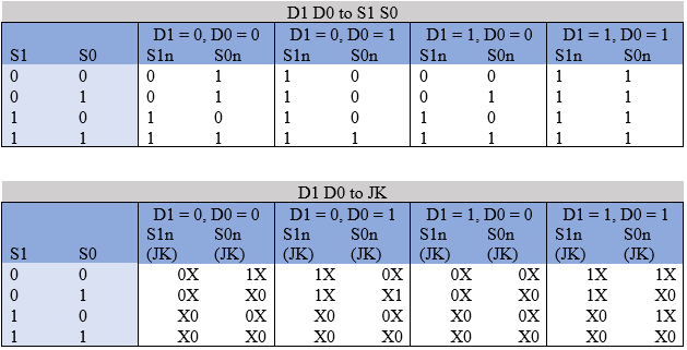
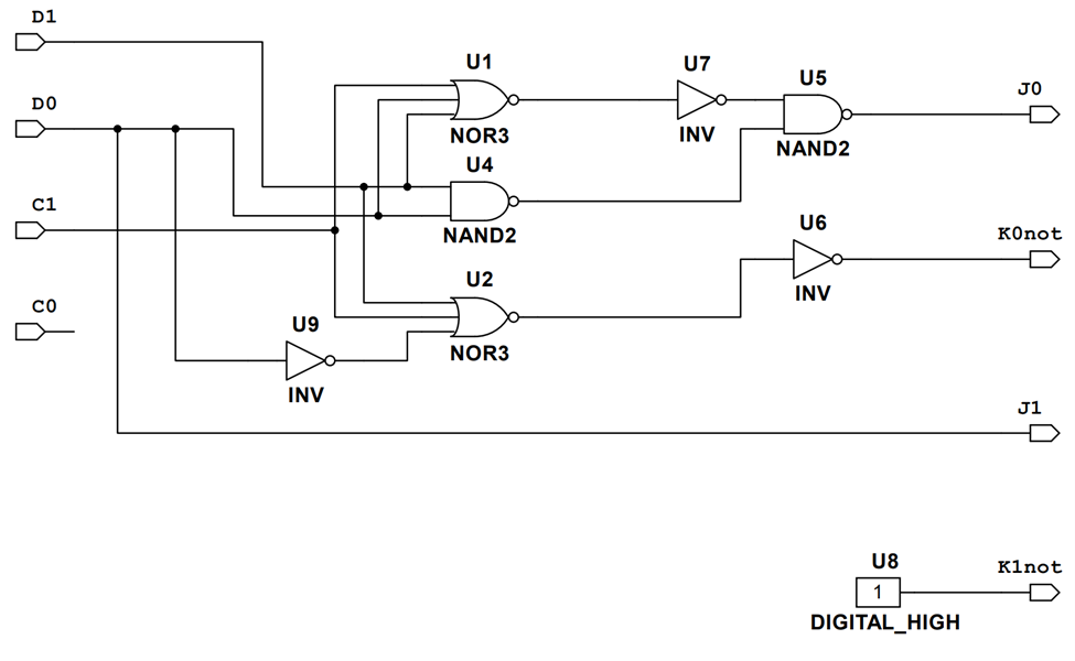
From the final state table, the excitation equations for the J and K inputs are derived using the K-maps as:
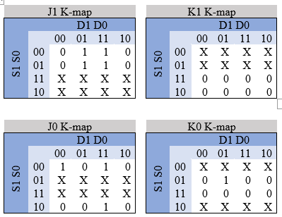
The four excitation equations were simplified using bubble pushing and the utilization of 3-input NOR gates. It should be noted that the K inputs need to be inverted to fit the 74HC109N J~K flip flops that are used. The resulting logic includes 2 3-input NOR gates, 3 NOTs, and 2 2-input NAND gates, see below. This will cost $7.40. In addition to the JK flip-flops, the reset input is needed. The ~CLR input on the flip flops need to receive a LOW signal to reset the flip flop so the input will need to be inverted. This will add one more NAND gate with the inputs tied together, adding $0.60 to the cost. The total cost is $8.00 on its own. In addition to the reset input, the CLK will need to be defined. To drive the clock, a 555 timer in its astable mode is used. The clock outputs approximately a 15 Hz square wave with an approximate duty cycle of 50%. The frequency is achieved by using a 1 kΩ resistor as R1, a 47 kΩ resistor for R2, and a 1 µF capacitor.
Display Driver Design
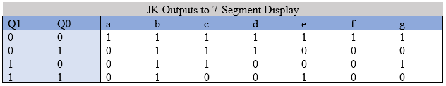
The binary states of the state machine need to be easily displayed to the user. The display is made by converting the binary state of the state machine to a letter representation on a seven-segment display. First, knowing what to display on the seven segments is needed to represent the F, C, and S characters. The F, C, and S are displayed by different combinations of the inputs a-g on the seven-segment display. With these inputs a truth table can be made to represent all of the state machines states, see below. A common anode seven segment display is used so a LOW signal will turn the display on.
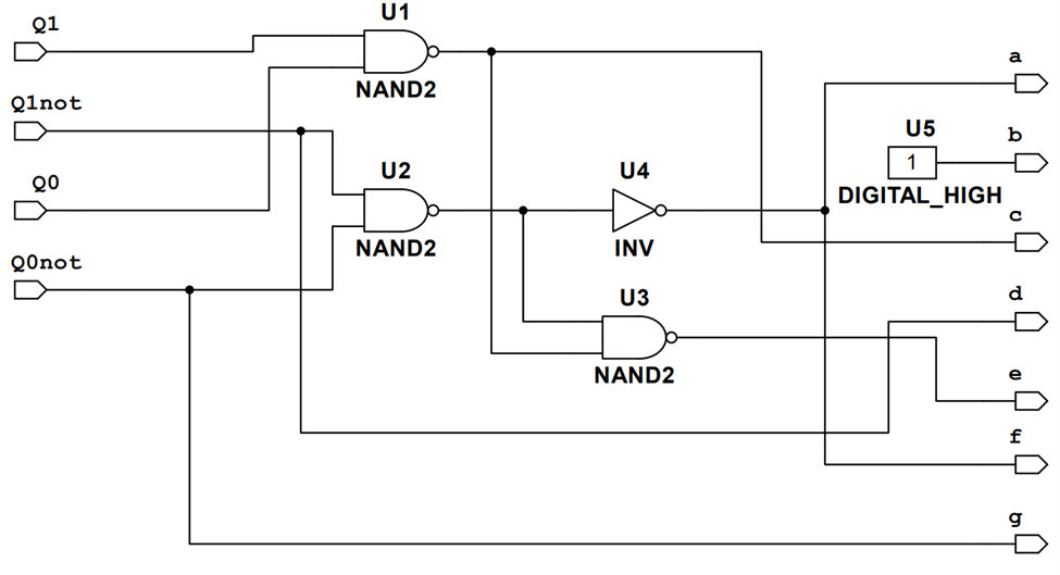
With the truth table defined, a K-map for each of the a-g inputs can be made. Once we have expressions for each letter input, we can simplify the resulting logic. This is done by bubble pushing and using the same gate, in this case majority NAND gates. The resulting logic uses 3 2-input NAND gates and one NOT gate, see below. This will cost $4.20. The a-g outputs are then put through a current limiting resistor of 370 Ω to the seven segment display inputs.
Final Design/Conclusion
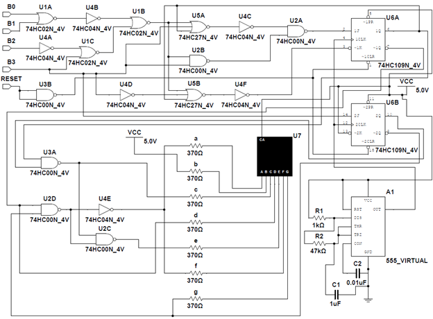
Once all the parts of the design were finished, it was time to piece them together. Connecting the different stages of the machine involved tying the outputs of the input logic to the excitation logic for the flip flops and wiring the state outputs to the seven segment display inputs. In this step the clock and seven segment display were also set up. For the final design, see schematic below, the total cost of the gates came out to $14.80.
Ethical Factors
This security system design protects valuables without violating the public health, safety, or welfare. This system serves as an alert tool only; it does not automate any sort of security or defense measures that could accidentally put someone in harm’s way. Furthermore, the response of this design is influenced only by the values from the sensors. Therefore, this design has no bias in its alert functionality. However, the sensors themselves and what is done with the information provided by this system are not necessarily free from bias. Thus, it is important to ensure the sensors as well as any security or defense measures do not threaten the public health, safety, or welfare. One possible solution for this is to use sensors which detect any movement within the ring, rather than trying to filter authorized versus unauthorized movement. On the opposite end, passive security measures such as lockdown of the area are good options for developing security without impeding public health, safety, and welfare.