Executive Summary
The goal was to design and build an automated, secure, storage system for a phone or similarly sized object.
The system would automatically open and close selected drawers and allow the user to set a passcode to open the drawer later.
The design explained below meets this goal and all customer requirements.
Requirements
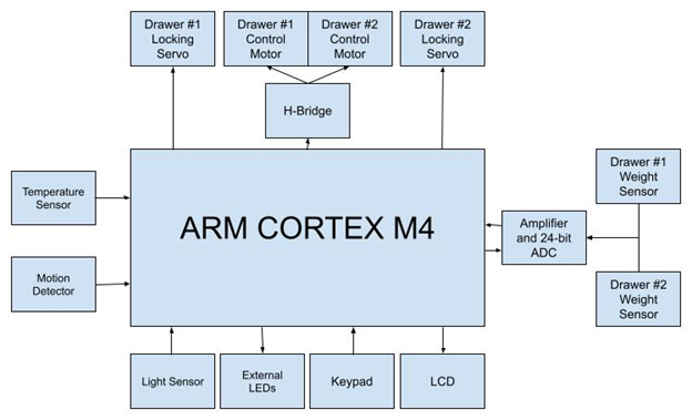
- Operate using an ARM Cortex M4 processor
- Operate drawers autonomously
- Be powered from a battery lasting a minimum of 2 hours standby time
- Have a power switch
- Have a master password for both drawers
- Have an LCD screen and keypad for drawer and password selections
- Gather and display temperature data inside the storage system using a temperature sensor and the LCD
- Not take more than one minute to open or close the drawer
- Fit phones up to 7 inches long and 4 inches wide
- Secure drawers when drawer is in locked state
- Keep locked drawers locked when powered off
- Have external lights for when dark
- Have drawer indicator lights for whether the drawer is occupied
- Appear off until user approaches
Design Overview and Analysis
This design is best explained through an example of use. First, a user walks up to the system. A motion sensor recognizes this and initializes the components previously turned off to save power.
The user chooses a drawer using the keypad as explained by the LCD. Assuming it is empty, the drawer is then opened using a rack and pinion gear system driven by a DC motor.
After the user places a device in the drawer, the device's presence is recognized by the load cell in the drawer and the user is asked to enter a passcode which will later unlock the drawer.
Once the passcode is entered, the drawer closes, locks using a servo motor, displays the temperature detected by the temperature sensor inside the system and returns to the "Select drawer" screen.
When the user is done, they walk away, and with no motion detected, the system enters a sleep mode which disables everything except the motion sensor and STM microcontroller board.
A photoresistor detects ambient light and turns on white LEDs if low levels of light are detected. Red and green indicator LEDs tell the user whether a drawer is occupied or vacant at a glance.
The system takes two power sources: a 9V battery converted to 5V with a linear voltage regulator, and 4 AA batteries to create a 6V source for the DC motors.
The drawers, DC and servo motor mounts, keypad mount, and rack and pinion gear system were all 3D printed for higher accuracy. The remainder of the enclosure was built out of ½" Baltic birch plywood.
System Block Diagram
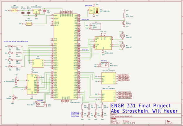
System Schematic
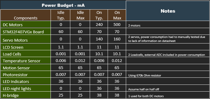
Power Budget
Raw Power Budget
Power Budget Based on Projected Usage
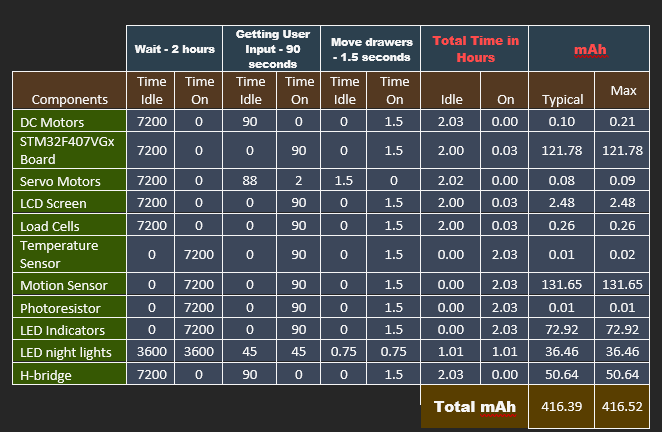
The power budget shows the system requiring a maximum of 416.52 mAh for a complete user interaction cycle.
Assuming a 9V battery has a capacity of 500 mAh, the system will last 500/416.52 = 1.2004 user interaction cycles assuming a 2 hour standby time.
The system's efficiency could be increased most easily by using more efficient LEDs, and possibly turning off power to the H-bridge when idle using transistors.
Conclusion
The lessons learned from designing, building, testing, and presenting this project come from a mix of what worked and what could have been improved.
One thing that worked well was using female header pins soldered to the perf board to connect the STM board temporarily.
On the other hand, several of the connections soldered to the perf board were longer than necessary and made loose connections to components or other wires.
Another good decision was using a mix of materials. 3D printed parts for the drawers and locking mechanism allowed for accuracy and replicable pieces that fit together perfectly. Using wood allowed for easy modifications and faster build time.
On the software side, using git for version control allowed the design to progress in stages and roll back to the most recent working version when all else failed, which was necessary once.