Introduction
This Verilog project demonstrates the running of a VGA monitor using the Basys 3 FPGA board.
Upon plugging the Basys 3 board into a capable VGA monitor, a 640x480 pixel display will appear with a white box in the center.
This box can then be moved around the monitor using 4 buttons on the Basys 3 board representing UP, DOWN, LEFT, and RIGHT. Each button press moves the box 20 pixels on the screen.
Design
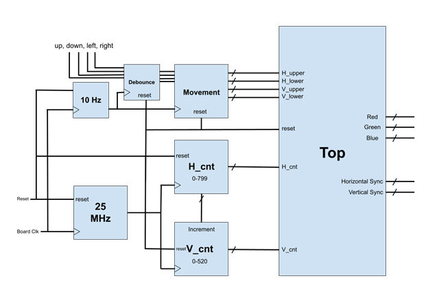
To run the display, two counters are needed: one for the vertical pixels (rows) and another for the horizontal pixels (columns).
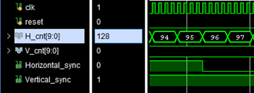
What will be called the H_cnt and V_cnt are the most important part of running the VGA display.
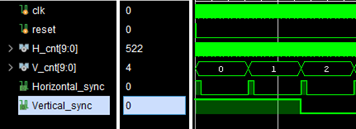
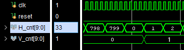
According to the Basys 3 documentation, to run at 640x480 px at a 60 Hz refresh rate, the H_cnt counts up to 800 and the V_cnt counts up to 521, each running at 25 MHz.
Each counter has four distinct sections: Sync, Front Porch, Display Time, and Back Porch.
The Basys 3 board has a 100 MHz crystal oscillator clock. A simple clock divider divides the frequency by four to serve as our 25 MHz clock.
The horizontal count updates every clock period, but the vertical only counts up after each horizontal row is complete.
To move the box, bounds H_lower, H_upper, V_lower, and V_upper are used. These shift according to UP/DOWN/LEFT/RIGHT inputs.
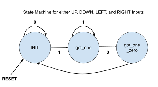
Because the Basys 3 board uses physical buttons, button debounce must be handled. A 10 Hz clock runs a 0-1-0 state machine to signify a button press.
Results
The design was tested with a testbench and then synthesized onto the Basys 3 board. The project uses 0.61% (126) of the board's LUTs and 0.28% (116) of the Slice Registers with a maximum clock frequency of 100 MHz.
Overall the project moved fairly smoothly. If I were to do the project again, I would set up more test scenarios in between steps of the design process and comment code along the way.
Improvements could include cleaning up the code, adding color changes, or adding an image reader instead of a plain square.